New designs for LED
copper heat sinks by Metal Injection Molding
17th Feb, 2017
The luminous flux of LEDs decreases with the rise of the operating
temperature and the dissipation of any heat generated is therefore,
aside from the efficiency of the LED chip itself, an essential part of
efficient LED systems. According to a recent report in LED Professional
it was stated that the thermal power loss of the LED, in comparison with
traditional incandescent lamps, is not radiated and therefore has to be
dissipated by thermal conduction from the LED into an applied heat sink.
The design of the LED heat sink has to ensure that the heat is conducted
through the material to the surfaces where it is transported to the
environment by convection and radiation. Thus, the design of a heat sink
has to fulfil two aims: good thermal conduction in the heat sink and a
design giving good thermal convection on its surfaces.

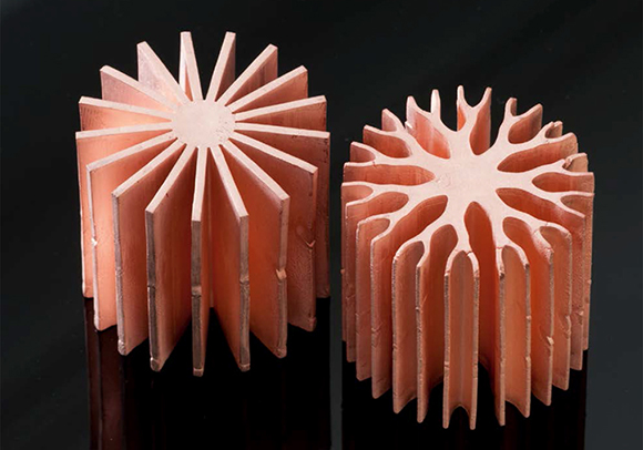
Fig. 1 Metal injection molded copper heat sinks after sintering.
The report, prepared by Christian Herbold and Cornelius Neumann from the
Light Technology Institute at the Karlsruhe Institute of Technology
(KIT) in Karlsruhe, Germany, analysed nature inspired shapes that would
combine high thermal performance with a high aesthetic value and which
could be mass produced economically. They used
Metal Injection Molding
to manufacture prototypes because of the ability of the process to
produce complex shapes in large quantities and with a high level of
design freedom. However, as MIM is mostly used for small parts with
typical weights ranging from 1 to 100 g, the challenge was to use MIM
for constructed heat sinks having two differing shapes using copper
powder and weighing around 330 g, as shown in Fig. 1. The left shape
reflects conventional heat sink design, whilst the right shape shows a
branched design.
The authors stated that Metal Injection Molding of such large sized heat
sinks raised two problems. The size makes it difficult to fill the whole
cavity with the viscous feedstock material before it solidifies in the
mould and, once filled, the large surface area causes significant
surface adhesion to prevent easy ejection of the molded part. The
cylindrical shape of the sample MIM heat sinks offers two advantages to
deal with these problems. Because of the geometry, the whole
cross-section area can be used for ejection. For this reason, the
pressure to push the molded part out of the cavity is applied to the
complete cross-section area and the risk of destroying the part during
ejection is reduced.
Furthermore, with this design the ejector can be used for compression
molding to support the improved filling of the cavity. However, the
authors also found that by slightly reducing the degree of filling the
mould could be ejected without breakage but that the molded heat sinks
then have some notches where the cavity was not completely filled.
For the MIM process, copper powder was mixed with a polymer as binder
and granulated to produce the feedstock which was injection molded on an Arburg Allrounder 570 S machine. The water soluble part of the binder in
the green part was removed in a water bath followed by thermal debinding
and sintering to produce the dense MIM Cu parts. During sintering the
heat sinks shrink evenly to about 85% of the size of the green part.
A shape distortion caused by the shrinkage can almost be avoided with an
appropriate sintering support that minimises friction between the parts
and the base. The shapes in Fig. 1 represent the constructed heat sink
geometries very well with the branched heat sink design based on an
approximate mathematical model and several thermal simulations. These
thermal simulations give the branched heat sink design an advantage of
8.4% for the given size. The notches seen in both heat sinks at half
height of the MIM parts were caused by the necessary reduced degree of
filling the mould. The branched MIM heat sink is 6% lighter than the
non-branched type.
The researchers at KIT will carry out further work to characterise the
MIM heat sinks for full heat dissipation properties. Optical
measurements with LEDs will supplement the results and a comparison to
standard heat sinks will be possible. They will also investigate an
additional design to be manufactured by MIM with the aim of combining
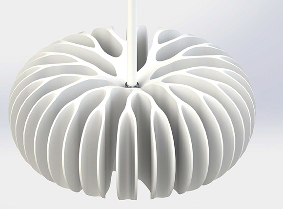
natural shapes with the shaping possibilities of the MIM process (Fig.
2).

Fig. 2 Possible heat sink design based on branched architecture.
They stated that heat sinks with larger diameters will extend the
advance in thermal resistance, and that the beauty of the branched
architecture is certainly worth thinking about for luminaires designed
on this principle, combining aesthetics and performance.

