Process Overview
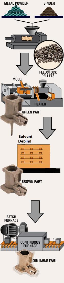 1.
Feedstock Mixing and Granulating 1.
Feedstock Mixing and Granulating
The first
step in the MIM manufacturing process is the production of the feedstock that
will be used. It begins with extensive characterization of very fine elemental
or prealloyed metal powders (generally less than 20 ìm). In order to achieve the
flow characteristics that will be required in the injection molding process, the
powder is mixed together with thermoplastic polymers (known as the binder) in a
hot state in order to form a mixture in which every metal particle is uniformly
coated with the binder. Typically, binders comprise 40% by volume of the
feedstock. Once cooled, this mixture is then granulated into pellets to form the
feedstock for the injection molding machine.
2. Molding
The next step is the
molding of the part in a conventional injection molding machine. The feedstock
pellets are gravity fed from a hopper into the machine’s barrel where heaters
melt the binder, bringing the feedstock to the consistency of toothpaste. A
reciprocating screw forces the material into a two-part mold through openings
called gates. Once cooled, the part is ejected from the mold with its highly
complex geometry fully formed. If necessary, additional design features not
feasible during the molding process (undercuts or cross holes, for example) can
be easily added at this stage by machining or another secondary operation.
3. Binder Removal
The ejected as-molded
part, known as a “green part”, is still composed of the same proportion of metal
and polymer binder that made up the feedstock, and is approximately 20% larger
in all its dimensions than the finished part will be. The next step is to remove
most of the binder, leaving behind only enough to serve as a backbone holding
the size and geometry of the part completely intact. This process, commonly
referred to as “debinding”, may be performed chemically (catalytic debinding) or
thermally, which in some cases may involve a solvent bath as the initial step.
The choice of debinding method depends on the material being processed, required
physical and metallurgical properties, and chemical composition. After
debinding, the part is referred to as a “brown part”.
4. Sintering
In this process, which is
performed in the highly controlled atmosphere of either a batch furnace or a
continuous furnace, the brown part is staged on a ceramic setter and is then
subjected to a precisely monitored temperature profile that gradually increases
to approximately 85% of the metal’s melting temperature. The remaining binder is
removed in the early part of this cycle, followed by the elimination of pores
and the fusing of the metal particles as the part shrinks isotropically to its
design dimensions and transforms into a dense solid. The sintered density is
approximately 98% of theoretical. The end result is a net-shape or
near-net-shape metal component, with properties similar to those of one machined
from bar stock. Of course, if necessary, post-sintering operations such as
coining, machining, heat treating, coating, and others, may be performed on the
part to achieve tighter tolerances or enhanced properties.
Markets include:
Automotive - Aerospace -
Medical - Business Machine
Computer Components - Hardware - Consumer
Goods
Manufacturing Capabilities
Molding Machines: capacity to 50 tons
Maximum Part Weight: 200g
In-House Secondary Operations/Post
Treatment
Heat Treating
Steam Treating
Vibratory Deburring
CNC Machining
Sizing/Coining
Mirror Polishing
Hairling Finish/Wire Drawing
Passivation
Laser Etching
Tool Building/Maintenance
In-House Quality Control and Metallurgical
Inspection
ISO 9001: 2000, ISO/TS 16949
Complete mechanical testing
facility including: Optical Metallographic Equipment, Vision System
Measuring Center, CMM, Optical Comparator, Micro-hardness and Apparent
Hardness Testers, Gear Checker, Surface Roughness Testers, Humidity Chamber,
Conductivity Meter. |

CAD/CAM
Precision Machining

Mirror Polishing
|